


Hardware components | ||||||
 |
| × | 1 | |||
 |
| × | 2 | |||
| × | 1 | ||||
| × | 1 | ||||
 |
| × | 1 | |||
| × | 1 | ||||
| × | 1 | ||||
| × | 1 | ||||
| × | 1 | ||||
| × | 1 | ||||
| × | 1 | ||||
 |
| × | 1 | |||
Software apps and online services | ||||||
| ||||||
 |
| |||||
| ||||||
 |
| |||||
| ||||||
Hand tools and fabrication machines | ||||||
 |
| |||||
 |
| |||||
 |
| |||||
 |
| |||||
MOTIVATION
I was developing a portable alarm device to install it in a house I have in a small village of Spain. One day, watching news on TV, I heard that and old lady had been found dead at home. She had been dead for weeks, maybe months, before someone rang her bell and noticed that something was wrong. Regrettably this was not the first time I knew about similar events. Besides, I have and old aunt who is been living alone for the last three years. Despite she wears an alarm button provided by the social care services, she once suddenly fainted and fell down on the kitchen floor and she could not press the button. When she happily woke up after hours, she was surrounded by a pool of blood.
Then I realized that just adapting the design, and doing some changes in the software, my simple and portable alarm system could become a useful way to avoid this kind of situations. It had to be a low cost and effective device, free of monthly fees.
The basic versión contains two PIR (Passive infrarred) and one door opening sensors. With regard to the control unit, you can choose the best option for every particular case. Elderly people on many occasions are not familiar with technology, so I first thought on Arduino MKR 1400 board to send alarm SMS in my particular case. You just need a prepaid SIM card to connect to a mobile phone network. But you can consider other boards if Internet is available at the house, or, should there is coverage in the area, think to use LPWAN connectivity. In this case, a push notification could be used to send the warning messages.
I decided to integrate two PIR motion sensors to dramatically reduce the number of false activations of this type of components. The sketch just consider a right motion detection when both sensors are activated simultaneously. I have implemented as well a software control that warns when the single activation of one of them occurs an abnormal number of times within a day. This fact could indicate a misfunction and that sensor should be replaced.
The door opening sensor makes the system more reliable and makes it useful even if there are pets living in the house together with the monitored person.
In order to forget about the maintenance I decided to make amodular device with no wireless battery supplied elements.
I think that the fridge is the perfect site to place it:- Since there is one fridge in practically every home and there is a wall plug close to it.
- Since it is normally used several times a day (breakfast, lunch, dinner)
- Since it has a door, and you have the certainty that the person will close it properly, so that the food and drinks inside do not spoil.
To make it work you first need to configure some items:
- You have to set the phone numbers of the people to whom the alert messages will be sent (relatives, neighbours, social care services…)
- Depending of the format of the messages you will also need to configure either one or several of the following parameters: the PIN number of the SIM card; the SSID and password of the Internet Access Point; the user and application keys for the push notifications, etc.
- You have to decide and configure what is the interval with no activity detected near the fridge (either movement or door opening) to trigger the alerts. Besides, you have to set the start time and the duration of the period during which the monitored person is sleeping. This way, during this period, the lack of activity will be ignored and alarms will not be generated. You need to know the sleeping habits of the person and adapt the time parameters to them in order to increase the operational effectiveness of the Geriatrino.
In my particular case I have set a lapse of time of five hours without any activity near the fridge to trigger the alerts. If you set a shorter period you may get a closer monitoring, but you can also get an unwanted number of false alerts if the person do not go to the kitchen in, let´s say, 3 or 4 hours.
I think that some changes could be done in the arduino sketch to get that the first lapse of time in the morning after the end of the rest period is half of the normal alert period set for the rest of the day.
I have developed two sketch versions:
In the first and simplest version you directly set all the above-named parameters by assigning the right values to the variables in the sketch, just when they are declared before the “set up()” function.
But I realized soon that it is a cumbersome process when you need to change or to update some of these values. You have to carry your laptop to the house where the Geriatrino is installed, connect both devices and perform the changes directly in the sketch using the Arduino IDE.
So, I thought that these settings could be done by anyone, whether he is a maker or not. Then I programmed a second and more complex sketch. In this case you use an app in a mobile phone or a tablet to do the configuration settings, stablishing a bluetooth connection with the Geriatrino. The “loop()” function changes almost nothing, but the “set up()” function becomes much more complicated. To program the app I used the MIT App Inventor platform.
The sketch available in Arduino Project Hub is the longest version, that is to say, you need to go to the App Inventor Gallery and find the “GERIATRINO_CONF_English” app. Then convert it to an ".apk" file and download and install it in your mobile phone or tablet. You can also directly download the ".apk" file from the Hardware-Schematics Section, of this project
(The app is only available for Android powered devices)
If you want to forget the app, you can find in the code, just before the setup() function, commented lines with the changes you need to do in the software to directly configure the Geriatrino using the Arduino IDE.
Finally I decided to make it work as an alarm system too. So, I added the software needed to get a multipurpose device. After entering the contact phone numbers in the app, you can select the operating mode: “Geriatrino mode” or “Alarm mode”. If the Alarm mode is the option, the device should not be placed on the fridge, and you have to find an appropiate door in the house so that the alarm function is carried out properly.
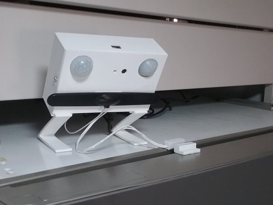
STEP 1Once you have got all the components you must integrate them in a container to make them work together.
Using FreeCAD 3D modeler I have designed a container that you can get in Thingiverse with the name“Geriatrino Frame Set”. It has three parts: Geriatrino Case, Geriatrino Cover and Geriatrino Leg. You can also download them from the Hardware-CAD section of this project.
When printing Geriatrino Cover, you will have to carefully remove with a cutter the thin layer of material to get the PIR holes and the built-in led hole. I had to do it this way to get better printing results with my basic 3D printer.
To mount the elements in this container you have to proceed as follows:
The lipo battery has to be placed at the bottom of the case, just in the center, so that the JST connector lays on the left top side, to easily meet the female JST connector of the MKR1400 board. I used double-sided adhesive tape to fix the battery to the bottom of the case.
I use a battery to make sure that the Geriatrino will still be operative for some hours in the event of a power cut.
Over the battery I stuck the minibreadboard with the Arduino board. If you are going to use my container design you have to stricly respect this layout, for all the holes on it have carefully been located to meet the following elements of the board: microUSB connector, SIM card slot, built-in led and built-in reset button. (you can add an external led and reset button, but I decided to reduce to the minimum the number of external elements).
Look in the pictures 4 and 5 that the MKR1400 board has been placed in the mini breadboard in a way that you have only a free column of pins on the left side, and two on the right side. The first male pins of the board (5 V pin and AREF pin) are inserted in the top row of the mini breadboard, this way you get three rows of holes free of connection at the bottom.
Look also in picture 5 at the detail of the bluetooth module placed on the right side, next to MKR1400 board.
You can follow the Geriatrinoschematics.fzz file from the Harware-Schematics section, to connect the components. I used some jumper wires to get more GND connections from the board GND pin to the right bottom side of the breadboard.
I am very bad at soldering and I have no experience In designing PCB´s. I am sure the layout can be improved to get more reliable connections and a smaller size for the device.
IMPORTANT.- Before placing the PIR sensors on the cover, do not forget to set their sensitivity adjustment and time-delay adjustment to the mínimum. To do it, place the PIR sensor with the white plastic cover facing down and turn the two orange wheel controls in counter clockwise direction to the left top. This way you get the mínimum sensitivity to reduce the number of false detections and the mínimum active output signal time (just a few seconds) to meet the software requirements.
After doing all the internal connections you just have to carefully match the case holes with the plastic clips of the cover, and finally screw on the two little screws on both sides.
After mounting the Geriatrino and before installing it, I recommend you to check that the sensors are correctly connected. Simple sketchs can be used to make sure they work properly
STEP 2I think that the best option to place the Geriatrino is at the top of the fridge, close to the door. This way it is more difficult to hit or move it, and you can easily lay backwards the power supply cable to meet the wall plug. If you choose this option you shoud print out two Geriatrino legs, and insert them in the available slots at the bottom of the Geriatrino case (use double-sided adhesive tape to stick the legs to the top fridge surface)
You can also place the device on the fridge door. If this is your choice, find in picture 4 the two neodimio magnets located at the bottom corners inside the Geriatrino frame. They thightly hold the device to the metal fridge door. I have perform tests and the magnets do not interfere with the PIR signals. Another option is to fix the Geriatrino using a double-sided adhesive tape. You also have to consider that the power supply cable has also to be fixed someway on the door surface and laid in a way that it does not hamper the door opening. If the cable of the power supply is not long enough you will have to use an extension cable to reach the wall plug.
STEP3
Once you have installed the Geriatrino you have to configure the necessary parameters to be set in the sketch.
To do it you have to go to App Inventor Gallery find the GERIATRINO_CONF_English app. Then convert it to an.apk file and download and install it on your mobile phone or Tablet. An easier option is directly download the ".apk" file from the Hardware-Schematics Section, of this project hub. After this, you are ready to start with the settings. (The app is only available for Android powered devices)
First connect the Geriatrino to the wall plug and make sure it is on.
Then open the app in your smartphone and follow the instructions. They are quite clear.
This app has been developped to configure an Arduino MKR1400 GSM board. So you will have to enter the phone numbers to send the SMS alert messages and the PIN number of the SIM card. After saving these data, you will be asked to select the operating mode:
- If you select the Alarm Mode you will not need to enter more settings and you will be directly asked to perform the sensor tests to make sure that the Geriatrino is fully operative. (Remember that if you use the device as a basic alarm, placing it in the fridge door is not usefeul and you have to find a proper site in your home, next to a door, to make it work effectively)
- If you select the Geriatrino Mode then you will have to set the inactivity period to trigger alerts, the current hour and minute, and the start time and duration of the rest period to inhibit the alarm messages while the monitored person is sleeping. Then you will be asked to perform the sensor tests.
If everything is correct, the phone numbers entered during the settings will receive a SMS with all the configuration information. If any of the tests failed and aditional SMS warning about it will be sent.
IMPORTANT REMARK.- Go to line 311 in the sketch to see that "+34" is added to every entered phone number. This is only valid if you are going to use the devices with spanish phone numbers. To make it work with any international phone number you should comment line 311, and in the app enter the full number, that is to say, "+XXYYYYYYYYY" (+xx is the internacional country code, and yyyyyyyy would be the phone number in every country)
Other boards can be used as control unit in the Geriatrino project. If you decide to use the Internet, or LPWAN networks, to send warning messages or Push notifications you will have to adjust the parameters in the app and in the Arduino sketch to make it work, but most of the loop() function will remain the same. You will only need to adapt the parts of software related to the message transmission.
I hope Geriatrino can be useful for you.


Comments